About the author : Dalibor
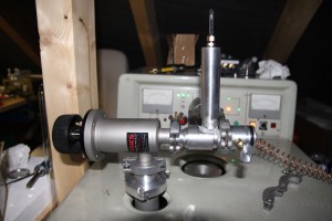
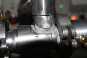
I finally made a progress in making my new gas filling manifold. I finally made it modular instead of brazing it together. I had really big problems with brazing the aluminum, I use the “Castolin 190 FB” solder and had to learn how to use it.. It is necessary to heat the aluminum sufficiently (approx. 600°C) so that the solder melts immediately after touching the joint. When the solder cools down, it makes white layer of flux what have to be filed off before another soldering – when You want to repair it. I initially used just gas-air torch, but it was not able to heat it enough, the solder stuck to the aluminum and formed a sphere instead of melting and flowing into every small cavity (it is a capillary type solder). Then I took the oxy-gas torch and the success came immediately! It was able to heat all the brazed part so that the solder made really nice and uniform weld (see the last picture)!
I checked the manifold for leaks and found nothing, so I let it pump for hour or so and it went below 10-4torr!
The needle valve is made according to Ron Soyland’s setup, just a short part from his email:
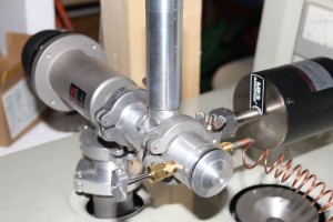
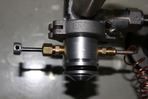
The manifold itself is made of a piece of 30mm dia. solid aluminum bar. I drilled holes through in three places for the valve stems, which I machined from mild steel. I then threaded the holes for brass fittings to hold the valve stem packing and on the other side the valve seat. The fitting for the seat has the inlet connection for the gas connection. I used 7mm copper tubing fittings (cheap and available) for all the connections. The connections to the tanks were a considerable problem. I tried using rubber tubing but had such leaks that it was impossible. I finally used capillary tubing like I saw someone on the internet doing. Great idea. The tubing is all soft soldered to the fittings so it is hermetic with no leaks at all. I mounted the baratron right on the side of the manifold since that baratron I use only for nixie work and do not have to have it removable to use elsewhere. The setup works great and allows me to add three types of gas at a time to a tube without having to remove connections and purge out the air. This is important if you are going to use an expensive gas like xenon, where a few purges of gas would cost a lot of $$$$!
The copper tubing fittings are for copper flare connections like in refrigeration work and fuel lines. The metric equivalent is 6mm. They should be commonly available at the hardware store or the auto supply store. Ebay is of course a source but there is the shipping.
The valve manifold is made from a piece of 30mm aluminum bar. It is made long enough to have however many valves you want. I have 3 on my manifold to allow helium, neon, and argon to be simultaneously admitted to the tube. The basic valve consists of a hole drilled straight through, one side to the other. This is about 4mm on my valve. Then, the same setup is used to drill the hole out larger for the threads of the fitting. These are 1/8 pipe threads on the USA system, but there is the equivalent pipe thread in metric. This is done on both sides of themanifold. This gives a hole with a bottom in it for the teflon washer to seal to.
The seal to the outside is done with the teflon washers. These are made thick enough such that when the fitting is tightened into the thread it compresses the teflon solidly thus forming a perfect seal. This took a bit of trial to find the thickness of teflon washer to do it just right without closing off the hole.
The seat of the valve is made by turning the stem into the teflon letting the point on the stem make the hole. This way the hole is exactly centered on the stem so it will seal properly. The steel easily punches the teflon.
The stem is machined in one operation on a piece of soft steel rod. It is easy to make. Be sure to support the end of the rod when machining so the diameter will be true all along the length. Polish the surface carefully where it will be sealing through the teflon.
The point on the stem is made to be a long taper with a sharp point so it will pierce the teflon when you make the seat hole.
You can see that the design is very easy and straight forward. If you do careful setups on your machine work the valve will be completely leak tight. The secret is using the compression of the teflon on smooth surfaces to produce a molecular tight seal.
The black gauge (second picture) is a baratron, this one measures vacuum on a scale 0-100 torr, so exactly what I need for nixie stuff.
This is a drawing of the needle valve made by Ron


